Bei mir zu Hause ist ein Logitech Harmony System im Einsatz, um die Geräte im Wohnzimmer zu steuern. Diese habe ich mit dem passenden Binding auch in openHAB integriert, was wunderbar funktioniert. Es lassen sich tolle Szenen erstellen, die einem das Leben leichter machen. Nun ist ein Harmony System nicht ganz günstig. Für das Wohnzimmer mit Fernseher, Anlage, Blueray, Amazon TV Stick und Apple TV lasse ich mir das gefallen. Im Schlafzimmer steht allerdings nur ein einsamer Fernseher. Ich möchte das Gerät über openHAB nur an- und ausschalten können. Also habe ich die passende Infrarot Fernbedienung einfach selbst gebaut.
Die Hardware der Fernbedienung
Als Basis für die Infrarot Fernbedienung dient ein ESP8266. Der Microcontroller verfügt über WLAN und kann daher sehr einfach in ein bestehendes Netzwerk eingebunden werden.
IR-Emitter 940 nm 17 ° 5 mm radial bedrahtet Vishay TSAL 6200
IR Signal der Original Fernbedienung auslesen
Damit wir später Signale senden können, die der Fernseher versteht, müssen wir zuerst einen IR Empfänger bauen, über den wir die Signale der Original Fernbedienung auslesen können. Hierzu benötigen wir lediglich den ESP8266 und den IR Empfänger TSOP.
Der Empfänger wird an Pin D5 (GPIO 14), GND, und 3,3V angeschlossen. Anschließend wird über die Arduino IDE folgender Code hochgeladen. Solltest du deine Arduino IDE noch nicht für den ESP8266 eingerichtet haben, empfehle ich folgende Anleitung von OpenDataLab.
|
1 2 3 4 5 6 7 8 9 10 11 12 13 14 15 16 17 18 19 20 21 22 23 24 25 26 27 28 29 30 31 32 33 34 35 36 37 38 39 40 41 42 43 44 45 46 47 48 49 50 51 52 53 54 55 56 57 58 59 60 61 62 63 64 65 66 67 68 69 70 71 72 73 74 75 76 77 78 79 80 81 82 83 84 85 86 87 88 89 90 91 92 93 94 95 96 97 98 99 100 101 102 103 104 105 106 107 108 109 110 111 112 113 114 115 116 117 118 119 120 121 122 123 124 125 126 127 128 129 130 131 132 133 134 135 136 137 138 139 140 141 142 143 144 145 146 147 148 149 150 151 152 153 154 155 156 157 158 159 160 161 162 163 164 165 166 167 168 169 170 171 172 173 174 175 176 177 178 179 180 181 182 183 184 185 186 187 188 189 190 191 192 193 194 195 196 197 198 199 200 201 202 203 204 205 206 207 208 209 210 211 212 213 214 215 216 217 218 219 220 221 222 223 224 225 226 227 228 229 230 231 232 233 234 235 236 237 238 239 240 241 242 243 244 245 246 247 248 249 250 251 252 253 254 |
/* * IRremoteESP8266: IRrecvDumpV2 - dump details of IR codes with IRrecv * An IR detector/demodulator must be connected to the input kRecvPin. * * Copyright 2009 Ken Shirriff, http://arcfn.com * Copyright 2017 David Conran * * Example circuit diagram: * https://github.com/markszabo/IRremoteESP8266/wiki#ir-receiving * * Changes: * Version 0.4 July, 2018 * - Minor improvements and more A/C unit support. * Version 0.3 November, 2017 * - Support for A/C decoding for some protcols. * Version 0.2 April, 2017 * - Decode from a copy of the data so we can start capturing faster thus * reduce the likelihood of miscaptures. * Based on Ken Shirriff's IrsendDemo Version 0.1 July, 2009, */ #ifndef UNIT_TEST #include <Arduino.h> #endif #include <IRrecv.h> #include <IRremoteESP8266.h> #include <IRutils.h> // The following are only needed for extended decoding of A/C Messages #include <ir_Coolix.h> #include <ir_Daikin.h> #include <ir_Fujitsu.h> #include <ir_Gree.h> #include <ir_Haier.h> #include <ir_Kelvinator.h> #include <ir_Midea.h> #include <ir_Mitsubishi.h> #include <ir_Panasonic.h> #include <ir_Samsung.h> #include <ir_Toshiba.h> // ==================== start of TUNEABLE PARAMETERS ==================== // An IR detector/demodulator is connected to GPIO pin 14 // e.g. D5 on a NodeMCU board. const uint16_t kRecvPin = 14; // The Serial connection baud rate. // i.e. Status message will be sent to the PC at this baud rate. // Try to avoid slow speeds like 9600, as you will miss messages and // cause other problems. 115200 (or faster) is recommended. // NOTE: Make sure you set your Serial Monitor to the same speed. const uint32_t kBaudRate = 115200; // As this program is a special purpose capture/decoder, let us use a larger // than normal buffer so we can handle Air Conditioner remote codes. const uint16_t kCaptureBufferSize = 1024; // kTimeout is the Nr. of milli-Seconds of no-more-data before we consider a // message ended. // This parameter is an interesting trade-off. The longer the timeout, the more // complex a message it can capture. e.g. Some device protocols will send // multiple message packets in quick succession, like Air Conditioner remotes. // Air Coniditioner protocols often have a considerable gap (20-40+ms) between // packets. // The downside of a large timeout value is a lot of less complex protocols // send multiple messages when the remote's button is held down. The gap between // them is often also around 20+ms. This can result in the raw data be 2-3+ // times larger than needed as it has captured 2-3+ messages in a single // capture. Setting a low timeout value can resolve this. // So, choosing the best kTimeout value for your use particular case is // quite nuanced. Good luck and happy hunting. // NOTE: Don't exceed kMaxTimeoutMs. Typically 130ms. #if DECODE_AC // Some A/C units have gaps in their protocols of ~40ms. e.g. Kelvinator // A value this large may swallow repeats of some protocols const uint8_t kTimeout = 50; #else // DECODE_AC // Suits most messages, while not swallowing many repeats. const uint8_t kTimeout = 15; #endif // DECODE_AC // Alternatives: // const uint8_t kTimeout = 90; // Suits messages with big gaps like XMP-1 & some aircon units, but can // accidentally swallow repeated messages in the rawData[] output. // // const uint8_t kTimeout = kMaxTimeoutMs; // This will set it to our currently allowed maximum. // Values this high are problematic because it is roughly the typical boundary // where most messages repeat. // e.g. It will stop decoding a message and start sending it to serial at // precisely the time when the next message is likely to be transmitted, // and may miss it. // Set the smallest sized "UNKNOWN" message packets we actually care about. // This value helps reduce the false-positive detection rate of IR background // noise as real messages. The chances of background IR noise getting detected // as a message increases with the length of the kTimeout value. (See above) // The downside of setting this message too large is you can miss some valid // short messages for protocols that this library doesn't yet decode. // // Set higher if you get lots of random short UNKNOWN messages when nothing // should be sending a message. // Set lower if you are sure your setup is working, but it doesn't see messages // from your device. (e.g. Other IR remotes work.) // NOTE: Set this value very high to effectively turn off UNKNOWN detection. const uint16_t kMinUnknownSize = 12; // ==================== end of TUNEABLE PARAMETERS ==================== // Use turn on the save buffer feature for more complete capture coverage. IRrecv irrecv(kRecvPin, kCaptureBufferSize, kTimeout, true); decode_results results; // Somewhere to store the results // Display the human readable state of an A/C message if we can. void dumpACInfo(decode_results *results) { String description = ""; #if DECODE_DAIKIN if (results->decode_type == DAIKIN) { IRDaikinESP ac(0); ac.setRaw(results->state); description = ac.toString(); } #endif // DECODE_DAIKIN #if DECODE_FUJITSU_AC if (results->decode_type == FUJITSU_AC) { IRFujitsuAC ac(0); ac.setRaw(results->state, results->bits / 8); description = ac.toString(); } #endif // DECODE_FUJITSU_AC #if DECODE_KELVINATOR if (results->decode_type == KELVINATOR) { IRKelvinatorAC ac(0); ac.setRaw(results->state); description = ac.toString(); } #endif // DECODE_KELVINATOR #if DECODE_MITSUBISHI_AC if (results->decode_type == MITSUBISHI_AC) { IRMitsubishiAC ac(0); ac.setRaw(results->state); description = ac.toString(); } #endif // DECODE_MITSUBISHI_AC #if DECODE_TOSHIBA_AC if (results->decode_type == TOSHIBA_AC) { IRToshibaAC ac(0); ac.setRaw(results->state); description = ac.toString(); } #endif // DECODE_TOSHIBA_AC #if DECODE_GREE if (results->decode_type == GREE) { IRGreeAC ac(0); ac.setRaw(results->state); description = ac.toString(); } #endif // DECODE_GREE #if DECODE_MIDEA if (results->decode_type == MIDEA) { IRMideaAC ac(0); ac.setRaw(results->value); // Midea uses value instead of state. description = ac.toString(); } #endif // DECODE_MIDEA #if DECODE_HAIER_AC if (results->decode_type == HAIER_AC) { IRHaierAC ac(0); ac.setRaw(results->state); description = ac.toString(); } #endif // DECODE_HAIER_AC #if DECODE_HAIER_AC_YRW02 if (results->decode_type == HAIER_AC_YRW02) { IRHaierACYRW02 ac(0); ac.setRaw(results->state); description = ac.toString(); } #endif // DECODE_HAIER_AC_YRW02 #if DECODE_SAMSUNG_AC if (results->decode_type == SAMSUNG_AC) { IRSamsungAc ac(0); ac.setRaw(results->state); description = ac.toString(); } #endif // DECODE_SAMSUNG_AC #if DECODE_COOLIX if (results->decode_type == COOLIX) { IRCoolixAC ac(0); ac.setRaw(results->value); // Coolix uses value instead of state. description = ac.toString(); } #endif // DECODE_COOLIX #if DECODE_PANASONIC_AC if (results->decode_type == PANASONIC_AC && results->bits > kPanasonicAcShortBits) { IRPanasonicAc ac(0); ac.setRaw(results->state); description = ac.toString(); } #endif // DECODE_PANASONIC_AC // If we got a human-readable description of the message, display it. if (description != "") Serial.println("Mesg Desc.: " + description); } // The section of code run only once at start-up. void setup() { Serial.begin(kBaudRate, SERIAL_8N1, SERIAL_TX_ONLY); while (!Serial) // Wait for the serial connection to be establised. delay(50); Serial.println(); Serial.print("IRrecvDumpV2 is now running and waiting for IR input on Pin "); Serial.println(kRecvPin); #if DECODE_HASH // Ignore messages with less than minimum on or off pulses. irrecv.setUnknownThreshold(kMinUnknownSize); #endif // DECODE_HASH irrecv.enableIRIn(); // Start the receiver } // The repeating section of the code // void loop() { // Check if the IR code has been received. if (irrecv.decode(&results)) { // Display a crude timestamp. uint32_t now = millis(); Serial.printf("Timestamp : %06u.%03u\n", now / 1000, now % 1000); if (results.overflow) Serial.printf( "WARNING: IR code is too big for buffer (>= %d). " "This result shouldn't be trusted until this is resolved. " "Edit & increase kCaptureBufferSize.\n", kCaptureBufferSize); // Display the basic output of what we found. Serial.print(resultToHumanReadableBasic(&results)); dumpACInfo(&results); // Display any extra A/C info if we have it. yield(); // Feed the WDT as the text output can take a while to print. // Display the library version the message was captured with. Serial.print("Library : v"); Serial.println(_IRREMOTEESP8266_VERSION_); Serial.println(); // Output RAW timing info of the result. Serial.println(resultToTimingInfo(&results)); yield(); // Feed the WDT (again) // Output the results as source code Serial.println(resultToSourceCode(&results)); Serial.println(""); // Blank line between entries yield(); // Feed the WDT (again) } } |
Vielen Dank an markszabo, der den Empfänger auf Github bereitstellt. Nachdem der Code hochgeladen wurde, musst du den seriellen Monitor öffnen. Sobald du nun eine Fernbedienung auf den Empfänger richtest und eine gewünschte Taste drückst, erhältst du verscheidene Daten, die ausgelesen wurden.
Unter anderem bekommst du die Rohdaten, die in etwa so aussehen:
|
1 |
uint16_t rawData[75] = {4556, 4450, 598, 1644, 598, 1644, 598, 1640, 602, 520, 598, 524, 598, 520, 598, 524, 598, 520, 596, 1644, 598, 1644, 598, 1640, 602, 522, 596, 524, 598, 520, 598, 524, 598, 520, 598, 526, 598, 1638, 602, 520, 598, 524, 598, 520, 598, 524, 598, 520, 598, 524, 598, 1640, 602, 520, 598, 1644, 598, 1644, 598, 1638, 602, 1640, 602, 1640, 602, 1640, 602, 520, 598, 524, 598, 520, 596, 526, 598}; // UNKNOWN B1E7875B |
Diese Daten sind wichtig für den Sender. Am besten du speicherst sie in einem extra Dokument, damit du sie später in den Sender Code einfügen kannst.
Der Sender
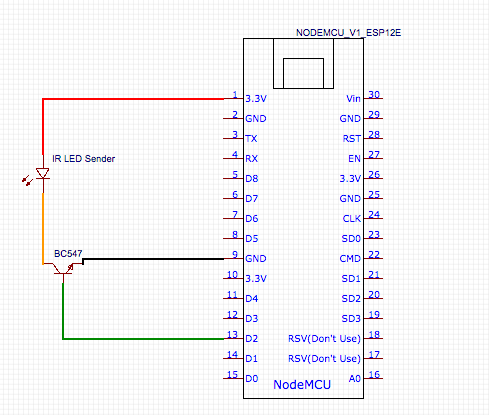
Sobald du den gewünschten Code der Fernbedienung herausgelesen hast, kann der NodeMCU zum Sender umgebaut werden. Hierzu benötigen wir die IR Sender LED und den Transmitter BC547. Diese werden wie im folgenden Schema beschrieben miteinander verbunden. Ein etwas anschaulicheres Bild findest du hier
Sobald alles korrekt verbunden ist, kann der neue Code für den Sender hochgeladen werden.
|
1 2 3 4 5 6 7 8 9 10 11 12 13 14 15 16 17 18 19 20 21 22 23 24 25 26 27 28 29 30 31 32 33 34 35 36 37 38 39 40 41 42 43 44 45 46 47 48 49 50 51 52 53 54 55 56 57 58 59 60 61 62 63 64 65 66 67 68 69 70 71 72 73 74 75 76 77 78 79 80 81 82 83 84 85 86 87 88 89 90 91 92 93 94 95 96 97 98 99 100 101 102 103 104 105 106 107 108 109 110 111 112 113 114 115 116 117 118 119 120 121 122 123 124 125 126 |
/******************************************************************* MQTT Infrared-Remotecontrol by zukunftathome https://zukunftathome.de *******************************************************************/ #include <ESP8266WiFi.h> #include <PubSubClient.h> #include <ESP8266mDNS.h> #include <WiFiUdp.h> #ifndef UNIT_TEST #endif #include <Arduino.h> #include <IRremoteESP8266.h> #include <IRsend.h> const uint16_t kIrLed = 4; // ESP8266 GPIO pin to use. Recommended: 4 (D2). IRsend irsend(kIrLed); // Set the GPIO to be used to sending the message. // IR SIGNAL SAMSUNG POWER uint16_t rawData[75] = {4556, 4450, 598, 1644, 598, 1644, 598, 1640, 602, 520, 598, 524, 598, 520, 598, 524, 598, 520, 596, 1644, 598, 1644, 598, 1640, 602, 522, 596, 524, 598, 520, 598, 524, 598, 520, 598, 526, 598, 1638, 602, 520, 598, 524, 598, 520, 598, 524, 598, 520, 598, 524, 598, 1640, 602, 520, 598, 1644, 598, 1644, 598, 1638, 602, 1640, 602, 1640, 602, 1640, 602, 520, 598, 524, 598, 520, 596, 526, 598}; // UNKNOWN B1E7875B const char* ssid = "YOURSSID"; //HIER DEIN WLAN EINTRAGEN const char* password = "123456789"; //HIER DEIN WLAN PASSWORT EINTRAGEN const char* mqtt_server = "broker.hivemq.com"; //DIES IST EIN ÖFFENTLICHER MQTT BROKER WiFiClient espClient; PubSubClient client(espClient); void setup_wifi() { delay(100); Serial.print("Connecting to "); Serial.println(ssid); WiFi.begin(ssid, password); while (WiFi.status() != WL_CONNECTED) { delay(500); Serial.print("."); } randomSeed(micros()); Serial.println(""); Serial.println("WiFi connected"); Serial.println("IP address: "); Serial.println(WiFi.localIP()); } void callback(char* topic, byte* payload, unsigned int length) { Serial.print("Command from MQTT broker is : ["); Serial.print(topic); Serial.println(); Serial.print(" publish data is:"); char* payload_str; payload_str = (char*) malloc(length + 1); memcpy(payload_str, payload, length); payload_str[length] = '\0'; if(String(topic) == "Haus/Fernseher") { Serial.print((String)payload_str); //Fernseher AN/AUS if(String(payload_str) == "power") { irsend.sendRaw(rawData, 75, 38); } } } void reconnect() { while (!client.connected()) { Serial.print("Attempting MQTT connection..."); String clientId = "YOU_CHOOSE_id"; clientId += String(random(0xffff), HEX); if (client.connect(clientId.c_str())) { Serial.println("connected"); client.subscribe("Haus/Fernseher"); } else { Serial.print("failed, rc="); Serial.print(client.state()); Serial.println(" try again in 5 seconds"); delay(6000); } } } void setup() { irsend.begin(); Serial.begin(9600); setup_wifi(); client.setServer(mqtt_server, 1883); } void loop() { if (!client.connected()) { reconnect(); } client.setCallback(callback); client.loop(); } |
Du musst noch einige Daten ändern, damit der Code bei dir funktioniert:
Füge den Code ein, den du mit dem Empfänger ausgelesen hast.
|
1 |
uint16_t rawData[75] = {4556, 4450, 598, 1644, 598, 1644, 598, 1640, 602, 520, 598, 524, 598, 520, 598, 524, 598, 520, 596, 1644, 598, 1644, 598, 1640, 602, 522, 596, 524, 598, 520, 598, 524, 598, 520, 598, 526, 598, 1638, 602, 520, 598, 524, 598, 520, 598, 524, 598, 520, 598, 524, 598, 1640, 602, 520, 598, 1644, 598, 1644, 598, 1638, 602, 1640, 602, 1640, 602, 1640, 602, 520, 598, 524, 598, 520, 596, 526, 598}; // UNKNOWN B1E7875B |
Füge deinen WLAN Zugang ein. Der MQTT Broker ist öffentlich und kostenlos. Solltest du einen eigenen Broker betreiben, kannst du auch diese Daten hier einfügen.
|
1 2 3 |
const char* ssid = "YOURSSID"; //HIER DEIN WLAN EINTRAGEN const char* password = "123456789"; //HIER DEIN WLAN PASSWORT EINTRAGEN const char* mqtt_server = "broker.hivemq.com"; //DIES IST EIN ÖFFENTLICHER MQTT BROKER |
Passe die Zahlen entsprechend an. Die vordere Zahl entspricht der Zahl in der eckigen Klammer des rawData. Hier [75]. Die Zweite Zahl entpsricht den Bits. Diese findest du beim Auslesen der Fernbedienung hinter Code (siehe Bild oben)
|
1 |
irsend.sendRaw(rawData, 75, 38); |
Um den Befehl via MQTT senden zu können, musst im Topic Haus/Fernseher den Befehl power publishen. Natürlich kann Befehl und Topic auch nach Belieben umbenannt werden.
Fernbedienung über openHAB ansteuern
Jetzt kann die MQTT Fernbedienung über openHAB angesteuert werden. So kann der Fernseher zukünftig über Regeln oder Szenen an und ausgeschaltet werden. Wie genau du das MQTT Binding in openHAB installierst und konfigurierst, kannst du hier nachlesen.
Du musst jetzt nur noch ein entsprechendes Item anlegen. In meinem Fall:
|
1 |
Switch Fernbedienung_Schlafzimmer_Power "FB Schlafzimmer An/Aus" {mqtt=">[mosquitto:Haus/Fernseher:command:ON:power],>[mosquitto:Haus/Fernseher:command:OFF:power]"} |
Das Item Fernbedienung_Schlafzimmer_Power kann nun in der Sitemap oder Regeln verwendet werden. Viel Spaß beim nachbauen.


Hallo Patrick,
vielen Dank für dein Tutorial. Es ist mein Einstieg in die Arduiono-Welt. Leier hat sich deine Anleitung ein Fehler eingeschlichen. Der Sketch nutzt den Pin D4. Du schließt den Empfänger jedoch an Pin D5 an.
VG
Oli
vielen Dank für den Hinweis. Ich habe direkt im Code angepasst 🙂
Hallo,
kannst du mir sagen wie das reconnect aussehen muss, wenn ich ein zweites gerät steuern will ?
void reconnect() {
while (!client.connected())
{
Serial.print(„Attempting MQTT connection…“);
String clientId = „YOU_CHOOSE_id“;
clientId += String(random(0xffff), HEX);
if (client.connect(clientId.c_str()))
{
Serial.println(„connected“);
client.subscribe(„Haus/Fernseher“);
} else {
Serial.print(„failed, rc=“);
Serial.print(client.state());
Serial.println(“ try again in 5 seconds“);
delay(6000);
}
}
}
Habe oben bei callback schon ein zweites gerät hinzugefügt.
Ändere ich im reconnect das subscribe von Haus/Fernseher auf das hinzugefügte funktioniert es.
Nur weiss ich nicht, wie ich bei reconnect die If abfrage aussehen muss.
MFG